English Italian German Dutch Spanish French Finnish Swedish
Phone/fax:
+372 698 74 66

Storage Tank Foundation Construction

To order

  • We will choose the optimal type of foundation in terms of price - quality;
  • We will develop a foundation design project;
  • We will use only certified materials;
  • We will build the foundation of the tank quickly and efficiently.

EuroTankWorks Construction & Assembling Department carries out the whole range of works on the construction of vertical storage tanks. The first step in this process is the construction of the foundation. This stage is very responsible, because mistakes made or poor-quality work will lead to a violation of the stability and reliability of the entire tank structure.

At the same time, the manufacture of foundations for tanks is an expensive event, therefore, the estimate of the entire construction will greatly depend on the foundation type chosen.

Therefore, during the construction of production facilities, the optimal way for the Customer to organize the construction of the tank farm will be to order the entire range of work from one professional contractor. EuroTankWorks has the necessary experience, equipment and staff of specialists who love and know how to work.

1. Geologic Exploration For the Tank Foundation Design

1.1. Geologic and hydro-geological research:

While planning the project for the foundation of a tank it is essential to study the geologic structure of the construction site and hydro-geologic conditions.

The soil exploration depth, as regards those, located lower the foundation base, depends on pressure, carried over by the construction to the basement. The depth is accepted to be either equal or more than the depth of the basement active area (compressible thickness of the basement soil).

Soil investigation is carried out by pitting and punching.

Shot hole is either a vertical or inclined mine working (tunnel) up to 40 m deep, which is done from the ground surface for the purpose of fossil minerals exploration, ventilation, mine drainage, material transporting, descent and ascent of people, etc. The cross-section area is equal to 0.8 – 4 m². The cross-section of the shot hole may be circular, rectangular or square-shaped.

Hole punching is the process of arranging of a directed mine working, long but small in diameter. The beginning of the hole at the ground surface is called well-head, the bottom is called bottom-hole.

The advantages of pitting are to be seen in the fact that the soil samples, taken from the shot hole, have undamaged structure; it is possible to determine the nature of soil, each layer’s thickness and their cross stratification along the walls of the shot hole, and there is a possibility to make compression resistance tests at the shot hole bottom.

The scope and type of soil investigation depend on monumentality of the installation, the nature and layering of the soil and ground-water level.

In the course of hole punching shot holes are made in important areas and the compression resistance of the soil is tested by trial load.

The location and the quantity of the shot holes or holes are determined in each and every case in connection with the planned shape and the dimensions of the installation, as well as by the soil smoothness.

As a rule the holes are made near the perimeter of the installation and its most important parts. Holes and shot holes are meant to draw up a grid on the site plan with the average square sizes of 25-30 m. More detailed investigation is carried out within the borders of the installation.

As a result of the research the plan and geological cross sections are made, stating the nature of soil, cross stratification and ground-water level. Based on the physical and mechanical characteristics, the estimated resistance parameters are set, and the reasonability to use the site for construction is determined.

On the whole, the soil investigation enables to collect the following information about soil and ground-water:

  • Lithological columns;
  • Physical and mechanical characteristics of the soil (mass density ρ, specific cohesion с, angle of shearing resistance φ, modulus of deformation Е, porosity ratio е, index of liquidity IL, etc.);
  • Estimated ground water level.

The amount of geological tunnels (holes) is determined by the square size of the tank and should be not less than four (one in the center and three near the wall, i.e. 0.9-1.2 of the tank radius).

In addition to holes it is also possible to explore soil by static probing.

In the course of engineering research one should provide the soil investigation at the depth of the active area (approximately 0.4-0.7 of the tank diameter) in the central part of the tank and not less than 0.7 of the active area in the wall part of the tank. In case of the piled foundation it is done at the depth of the active area lower than the contingent foundation base (pile point).

For the areas of permafrost soil engineering and geocryological research is usually done. This is meant to provide information on composition, state and characteristics of the frozen and melting ground, cryogenic processes, including forecasts for the changes of the engineer and geocryological conditions for the planned tank construction.

1.2. Considering seismic impact on the tanks’ foundations

Areas with high level of seismic activity demand geophysical investigation of the foundation soil.

The result of the investigation before designing oil tank basement enables to calculate the foundation’s seismic resistance within the first group of the extreme limit state under maximum load in their special connection to the most loaded part of the natural foundation. Its stability should be guaranteed under the outer edge of the circular foundation at the seismic forcecrest valie and the standard value of the safety index, equal to 1.2.

2. Tank Basement Construction

The planned construction should be considered together with its basement, as the weight of the installation and other possible operation impact make the basement soil suffer additional pressure, become distorted (condensed and subsided) and thus influence the whole installation.

The foundation basement can be represented by either of the two types: earth foundation and artificial subgrade.

2.1. Earth foundation (natural base)

This includes basements with the soil located under the foundation base in their natural occurrence.

Embankment.Embankment.Embankment.


Only soil with enough compression resistance (endurance and mass density) can be used as natural oil tank base, provided that its distortion (subsidence) does not exceed the cutoff value under the installation load through the foundation base.

In order to provide the necessary steadiness and endurance of the constructed installation, the soil of the earth foundation should show the following basic features:

  • Low and even compressibility, i.e. high mass density, ensuring low and even subsidence of the installation;
  • Should be undissolving under the influence of ground-, rain- and melt-water.

In the course of tank operation while the basement soil’s density increases, the foundation subsidence takes place. If the strain of the foundation base exceeds the estimated resistance, the basement soil receives intermittent congestions, and the foundation has different subsidence ratio at its various points. This subsidence may be extremely big and may lead to the loss of steadiness of the on-foundation part of the installation or achieving the extreme endurance limit level.

In order to determine the influence of subsidence on the installation, engineering calculation of basements and foundations is made. The basement estimating calculations include determining of pressure (stress) of the soil under the foundation base and the level of subsidence of the basement soil, that may be shown under this stress.

If prohibitive rates are received for the subsidence, special measures should be undertaken for the sake of reducing the strain and bringing subsidence to acceptable limits. The latter may be achieved by enlargement of the foundation base or choosing an artificial subgrade.

2.2. Earth foundations with bedding course

To ensure reliability and economic effectiveness of the construction framework an intermediate scheme is often used – the one between a natural base and an artificial subgrade. It is an earth foundation with sand or soil bedding (cushion) provided in the form of basement bedding course.

It is also possible to arrange a concrete ring under the tank wall. (See pic.1.).

Basement bedding course is meant to provide the following:

  • Allocation of the tank metal frameworks’ pressure on the basement;
  • Bottom drainage;
  • Ensuring the bottom corrosion preventive functions.

The following material can be used for the bedding course:

  • Compacted coarse sand;
  • Crushed stone;
  • Gravel;
  • Sand-and-gravel mixture.

The bottom corrosion preventive protection is provided by a hydrophobic layer with binders, put on top of the bedding course.

As a rule, the height of the bedding course is equal to 0.2 – 2.5 m. This depends on the results of the engineering and geologic exploration of the construction site.

The surface of the bedding course is inclined from the centre to the edges. It is meant to balance the uneven subsidence of the tank and to ensure the influx of the stored product to the pumping devices. In practice the tank bottom subsidence may amount to 2 m, that is why raising of its central part may become the key factor of the long operation life period of the construction.

If the construction site has soft or heaving soil at little depth (up to 3 m), which is characteristic of areas with deep seasonal soil freezing, it is possible to replace them with local densification of sand or clay soil. If the soft soil layer is more thick this method does not often show economic effectiveness, as the current cost of tank leveling increases.

2.3. Artificial oil tank base (subgrade)

Artificial subgrade includes:

  • Artificially reinforced basement soil (either by densification, chemical fixing or installing concrete or sand piles);
  • Piled basements and deep foundations, distributing the construction load to the more durable soil at the deeper level from the ground surface;
  • Others.

2.3.1. Types of artificial subgrade for different kinds of soft soil

Subsiding soil demands elimination of subsiding features within the whole subsiding thickness or arranging piled foundation that go through the whole subsiding thickness.

Dilative soil demands the following measures, if the estimated deformation of the basement exceeds the extreme parameters:

  • Full or partial replacement of the dilative soil by the non-dilative one;
  • Applying balancing sand cushions;
  • Arranging piled foundation.

In the course of designing the oil tank basements for water-saturated silt-loam and biogenous soil and slime a certain set of procedures should be implied if the estimated deformation of the basement exceeds the assumed parameters:

  • Arranging piled foundation;
  • Full or partial replacement of the biogenous soil by sand, crushed stone or gravel, etc.;
  • Pre-construction densification of the soil by temporary additional load (it is allowed to perform densification of the soil by temporary load in the course if hydro-testing of the tanks according to the special program).

In the course of designing the oil tank basements for anthropogenic soils the following procedures should be provided if the estimated deformation of the basement exceeds the assumed parameters:

  • Arranging of complete iron-concrete slab with a slide seam between the tank bottom and the top of the slab;
  • Applying flexible joints (balancing systems) at the junction points;
  • Arranging tank leveling devices.

While developing the oil storage tank foundation design for carstified territories it is necessary to perform the procedures, meant to avoid karst deformation:

  • Filling karst hollow bags;
  • Cutting the karstland by deep foundation;
  • Fixing the karstland or/and upper-level soil.

Installation of tanks in the areas of active karst processes is not allowed.

In piled foundation the pile ends are earthed in low-compressible soil and provide meeting the requirements for the extreme tank deformation. The piled foundation can be either under the whole body of the tank – “pile field” or “circular” – under the tank wall.

If these measures do not help to avoid exceeding the extreme basement deformation or if they appear to be unreasonable, it is necessary to provide special devices (compensating pipes) at the junction points and tank leveling devices which enables stability and reliability of the joints in the course of tank subsidence.

In areas with permafrost soil while using them according to the first pattern (keeping the soil frozen within the period of construction and operation) it is essential to protect them from the above-zero temperatures of the stored product. This is achieved by making aerated under-floor space (“elevated grillage”) or by using heat-insulating materials combined with forced soil cooling – “thermostabilization”.

2.3.2. Methods of oil tank basement soil reinforcing

Construction sites with high thickness of soft soil can show sufficient uneven subsidence of the basement, which influences the subsequent tank operation. That is why special basement preparations should be performed while installing tanks on soft soil.

Soil beddings must be made of per-layer optimum moisture compressed soil with the modulus of deformation after reinforcing not less than 15 mega Pascal and the coefficient of consolidation not less than 0.90.

The inclination of soil bedding should not exceed 1:1.5. The width of the horizontal part of the bedding surface outside the edges should amount to:

  • 0.7 m – for tanks of loading capacity not more than 1000 m³;
  • 1.0 m – for tanks exceeding 1000 m³;
  • 1.0 м. – regardless of loading capacity for construction sites of estimated seismic activity of 7 and more balls rated on Richter scale.

The bedding surface outside the tank perimeter (horizontal and inclined parts) should be protected by paving.

There are various methods of basement soil reinforcing (without its replacement).

2.3.2.1. Method of tentative tank filling

Tentative (sometimes partial) filling of the tank is used as one of the relatively often applied methods of basement soil reinforcing and improving its construction features. This method is quite easy and cheap, as the useful load of the tank on the basement is higher than that of the construction frameworks’ weight and it can be quickly applied and removed.

It should be noted that, along with relatively low cost, the use of this method implies certain technological difficulties and is time-consuming, so it is reasonable only provided that there is sufficient time availability.

2.3.2.2. Method of deep water drawdown

As a means of oil tank basement compression this method may be successfully applied at the sites with layers of soil, showing high water loss. This method is especially effective in tank installation in areas of severe climate conditions, because water pumping can be done all the year round from the soil layers, located lower the seasonal frost-penetration level.

Water drawdown installation includes sumps, one of which is usually located in the centre of the basement and others – along the edge. Maximum drop in of the ground water level amounted to 8 m, pumping was carried out before installation and in the period of hydraulic testing.

2.3.2.3. Method of basement compressing with bund

The oil tank basement may be compressed by the weight of a bund of several meters high. The load is kept for several weeks before starting the installation. Bunds are sometimes made of variable height to consider the deviations in the thickness of soft soil to make sure that the subsidence will be even.

This method may give positive results provided that the balance weight is 1.5-2 times more than the load of a full tank. That is why in the course of basement preparation for large tanks it will be necessary to make bunds of sufficient height (up to 8-10 m) and the period of keeping the load may last several months. It will also be necessary to arrange the bund on a bigger area than that of the exact tank installation to ensure that the wall basement receives the needed compression. Thus, the use if this quite effective method is connected with a large scope of groundworks, which is especially difficult in areas of severe climate conditions and long frost period.

With the development of tank construction, methods of basement soil compression are often used in combination with the vertical draining. In this case special mechanisms and technological schemes are used to allow arranging vertical drain canals made of cardboard or plastic, as well as sand piles-drain canals in different soil conditions.

2.3.2.4. Method of heavy tampering compression

While preparing basement of subsiding soil it is often possible to use the method of heavy tampering. In this case a heavy load is dropped to the site from the height of several dozens meters. This method of basement preparation is considered competitive when a group of large tanks is being installed.

2.3.2.5. Methods of chemical and thermal soil fixing

In practical construction there were situations when the soil was fixed by injecting chemical substances, for example electrochemical fixing with the liquid calcium chloride. This method is rather expensive and its application on sites having soft soil at sufficient depth has obviously few perspectives.

Soft soil may also be burned at sufficient depth (10 m and more). As the thermal burn is connected with large fuel consumption (80-100 kg of masut for 1 m of hole length), the current level of fuel prices makes this method extremely expensive and unreasonable for application.

3. Tank Foundation Construction

Gravel foundation.Gravel foundation.Storage tank foundation.Storage tank foundation.Foundation is the part of construction that transfers the load of the installation weight on the basement soil and distributes the load on such area of the basement, which allows the foundation base pressure not to exceed the estimated levels. The design plan may imply different types of foundation: complete plates (slabs) under the whole structure, strip foundation – only under the walls, and pier foundation in the form of separate supporting structures. The choice of the foundation type depends on soil resistance to compression, its heaving properties in seasonal freezing, depth of its occurrence, the planned shape of the construction, and also on the weight load parameters and the scheme of its transfer to the basement soil.

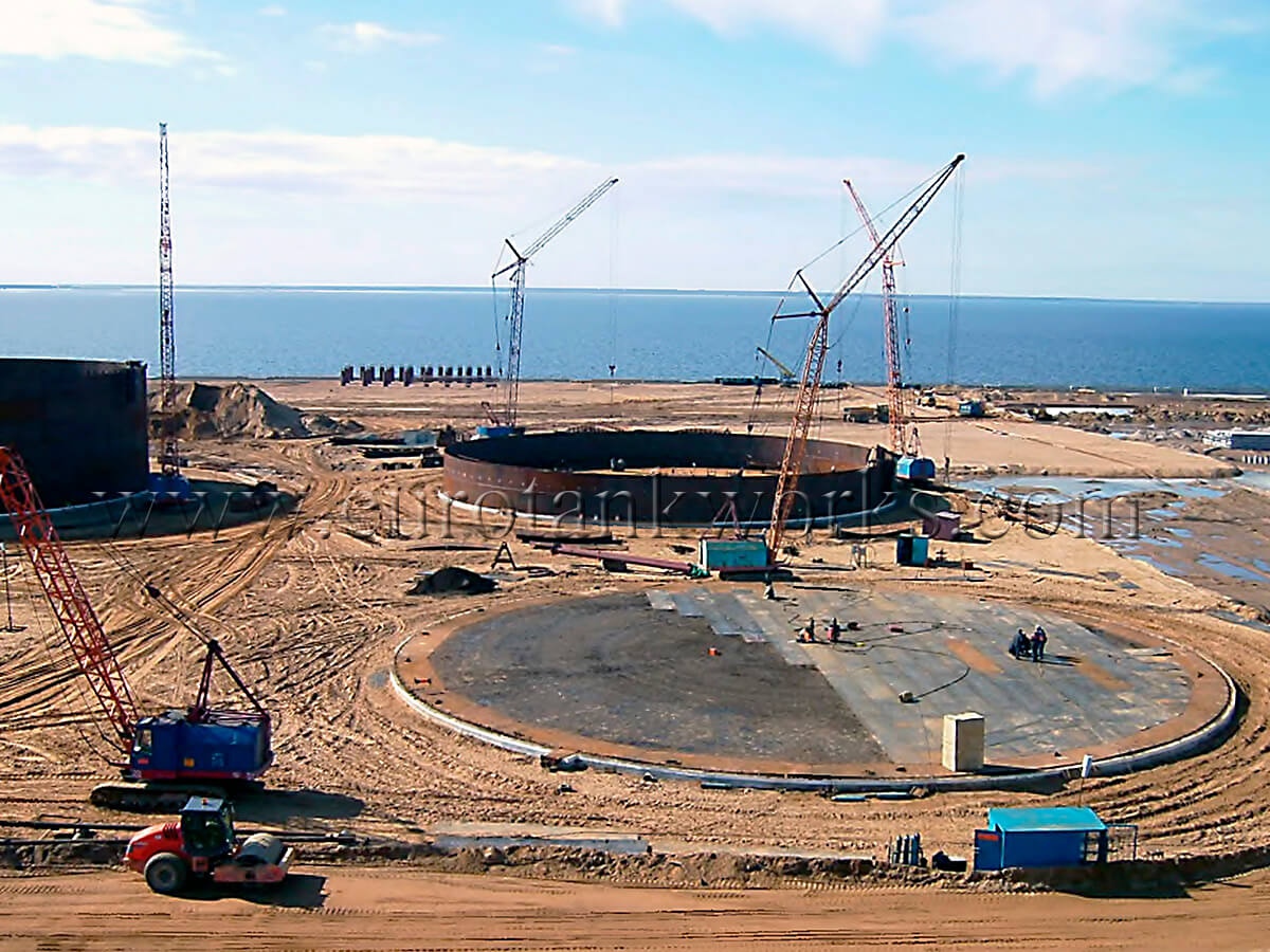
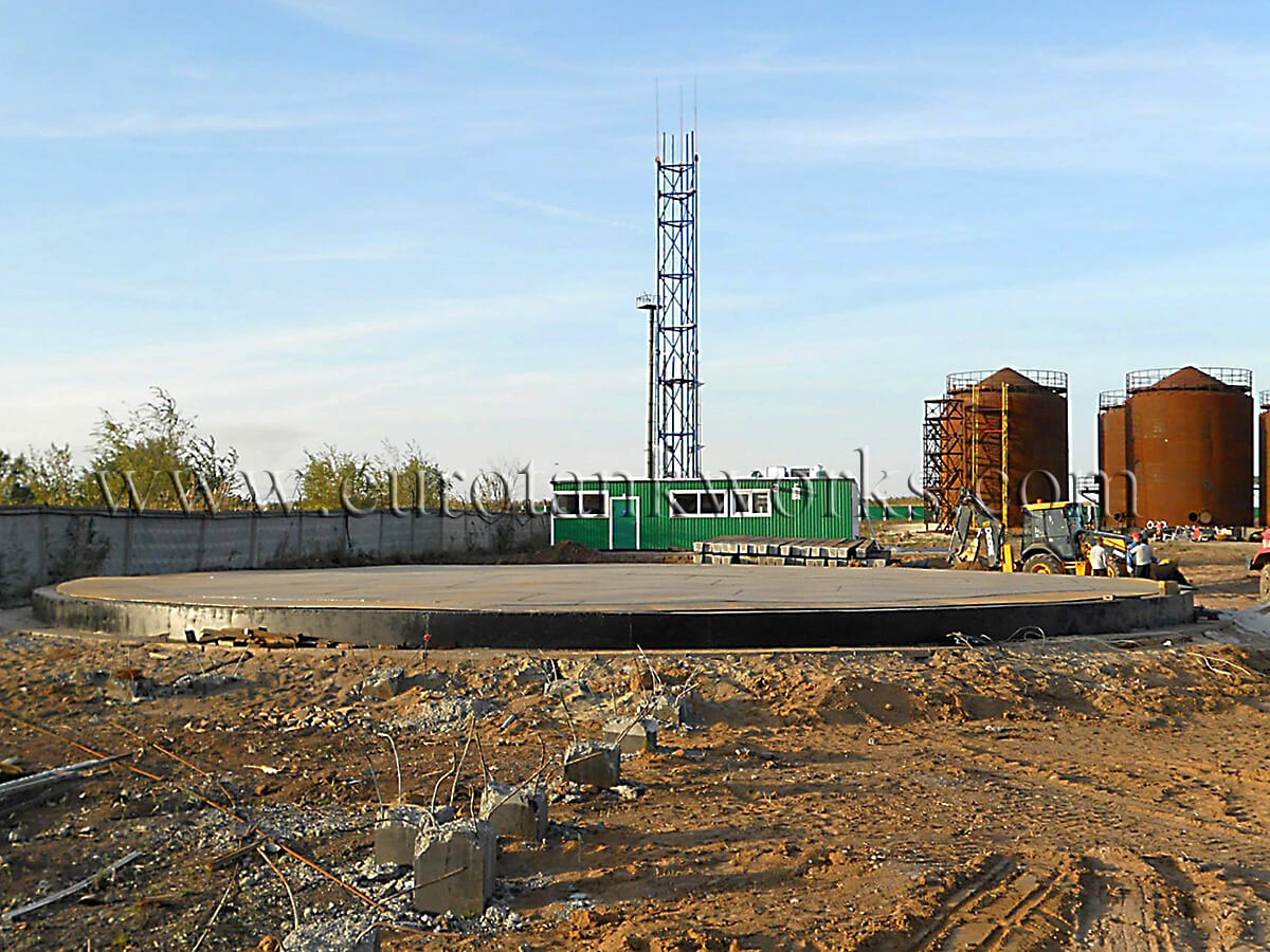
While arranging the tank foundation it should be foreseen to perform special measures to ensure diverting of ground water and precipitation from under the tank bottom.

All foundation arrangements should be made before starting its installation. The planned basement perimeter walk (paving), the shaft staircase foundation, the piers for pipelines are recommended to be installed after assembling the tank’s metal frameworks.

There is a wide variety of tank foundation types in modern construction practice. The choice of the most efficient type depends on the loading capacity and engineering-geologic conditions. The use of foundations on natural base, partially or fully without piles under the tank bottom, seems to be the most preferable due to low cost.


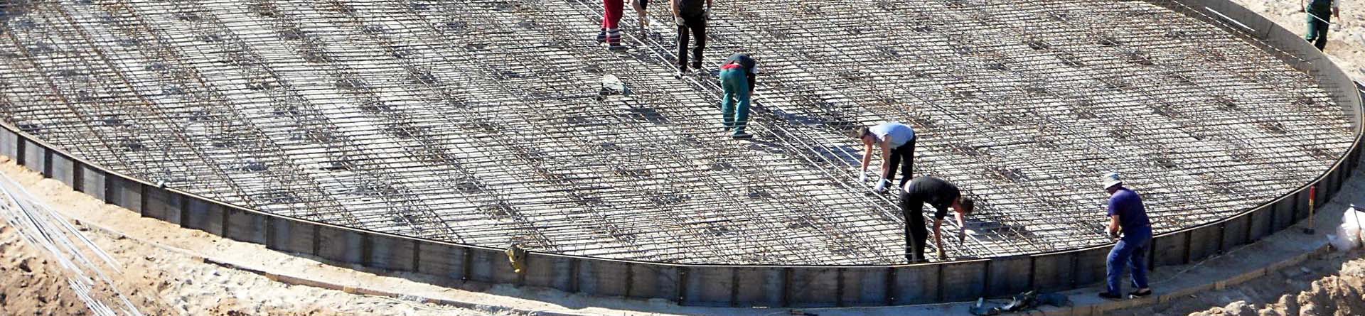
3.1. Circular (ring) tank foundation

Girder (wall) foundation is often applied combined with the basement bedding course. Soil bedding (both with and without an iron-concrete ring under the tank wall) may be used as tank foundation… An iron-concrete foundation ring is installed under the tank wall for tanks with loading capacity exceeding 2000 m³. The ring has to be not less than 0.8 m wide for tanks with less than 3000 m³ loading capacity, and it should not be less than 1.0 m for tanks with capacity exceeding 3000 m³. The thickness of the ring should not in any case be less than 0.3 m.

Tank foundation.


As practical experience shows, this construction of the foundation provides stability of bedding course only, at the same time not increasing rigidity of the junction of the tank wall and its bottom. This construction also does not affect the unevenness of subsidence of the tank basement.

In certain conditions the foundation in the form of a circular wall is also effective. It cuts through upper layers of the basement soil and may transfer the load to the underlying dense layers.

The requirements of the standards demand to install foundation rings for all tanks irrespective the loading capacity installed in areas of estimated seismic activity equal and exceeding 7 balls rated on Richter scale.The width is supposed to be not less than 1.5 m, the ring thickness is implied not less than 0.4 m.

The foundation ring is designed for basic stress (load) combination. In case of construction sites in seismic areas (7 balls and more on Richter scale) specific stress combination is also considered.

Crushed stone ring foundation

There is also practice to use circular foundation of gravel or crushed stone along with the bedding course; and also iron-concrete circular foundation, located directly under the tank wall, as well as foundation in the form of iron-concrete breast wall, located in the outer space of the tank.While arranging the ring in the form of breast wall the bedding course is made of sand-gravel mixture or gravel.

Iron-concrete foundation is usually made of cast reinforced concrete with rectangular cross-section. Sometimes the foundation is made on natural base with crushed stone ring under the wall. Such foundation is effective in case of anticipated subsidence not more than 15 sm. This is its main peculiarity: crushed stone is used instead of sand directly under the wall to arrange crushed stone or gravel bund not less than 60 sm high with the top width of 1-2 m.Crushed stone is laid in layers of 20 sm each, thoroughly tampered. Directly under the bottom on its full square the crushed stone layer is arranged, not less than 10 cm. Drain pipes of around 9 cm in diameter are installed additionally.


Reinforced concrete ring foundationThe following construction schemes may be applied for wide tanks: sand bedding course is arranged under the bottom and either iron-concrete or crushed stone circular foundation is installed under the wall, depending on the soil conditions.

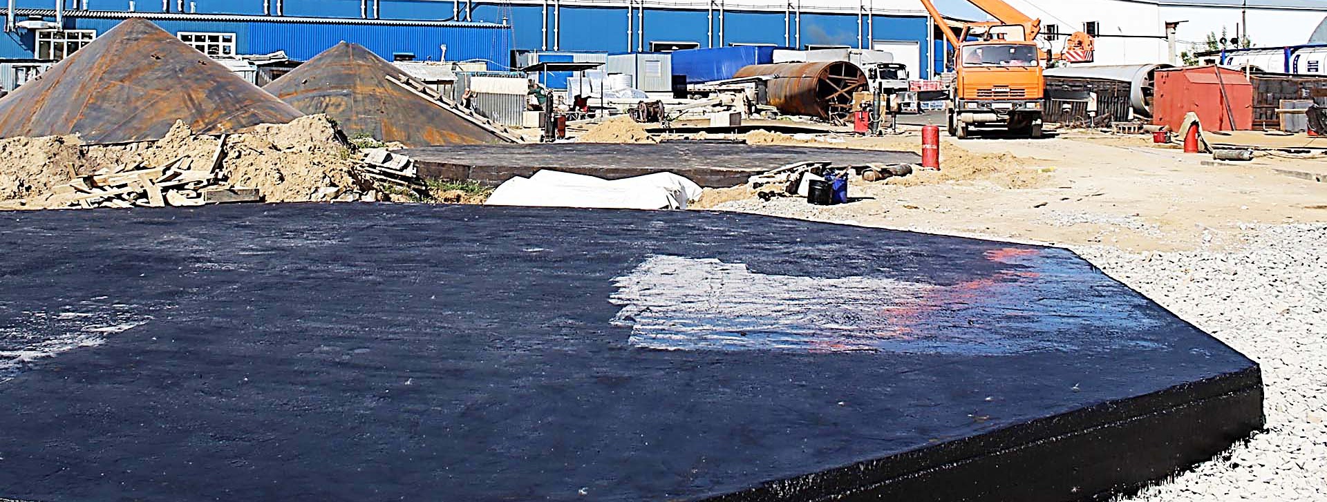
The under-wall bedding course on the outside of foundation is installed with slight slope of 1:5, which is supported by the breast wall in its lower part.The bund is equipped with drain pipes and protected by the asphalt coat (dope).There is a damping asphalt layer not less than 20 sm between the bottom and iron-concrete surface of the ring foundation.

Additional measures of foundation reinforcing are constantly developed to increase safety of large tanks.

The sand-gravel cushion is covered by mixture of sand, crushed stone, asphalt emulsion and cement, compressed by rolling afterwards. The received surface takes away part of the cushion load, transferring it to the iron-concrete ring.

The foundation can be also made in the form of iron-concrete slabs. In these cases tank stands on an iron-concrete slab, installed either on the basement surface or lower the grading elevation. The iron-concrete wall along the perimeter of the plate is earthed lower its foundation bed and serves for reducing the lateral shift of the soil.

Ring foundationReinforced concrete slab foundationReinforced concrete slab foundation

3.2. Piled tank foundations

3.2.1. Traditional approach to arranging piled foundations

This type of foundation is quite often used at sites with soft soil. Construction experience in industrial and civil building shows that in most cases piles can help to achieve the acceptable level of construction subsidence. However, the practice of piled foundation in tank construction shows that it does not always help to get the desired result. Along with this, such type of foundation is quite money-consuming and the level of capital expenditure is almost equal to the cost of the metal frameworks itself.

It was registered not for once, that tanks on piled foundation showed higher subsidence than it had been planned in the course of hydro-tests, amounting to half of the subsidence level, foreseen for the whole period of tank operation life.

The ineffective use of piled foundation in tank construction may be explained by the following: in case of large tanks, piles with the usual length of 0.25 of the tank diameter and less, are located in the area of maximum vertical strain at the tank basement. That is why reducing the strain by making the foundation deeper does not have sufficient influence on such foundation’s subsidence.

The use of piled foundations may even be dangerous when there are layers of higher compressibility at big depth at the tank basement. It is not always possible to reveal such layers due to technical difficulties, connected with punching and taking the soil samples at deep depths.

Specialists tend to think that piled foundation with monolithic grillage represents a sufficiently rigid construction. There are certain results of subsidence surveys for tanks with piled foundation, that convincingly deny this point of view.

3.2.2. Foundations with piles under the whole bottom and with iron-concrete grillage

Pile foundation

As a result of many years’ experience of tank construction on soft water saturated soil there are several effective measures of basement preparation. The main goal of these measures is to compress the soft soil before starting construction procedures, which is aimed at improving the soil’s physical-mechanic characteristics.

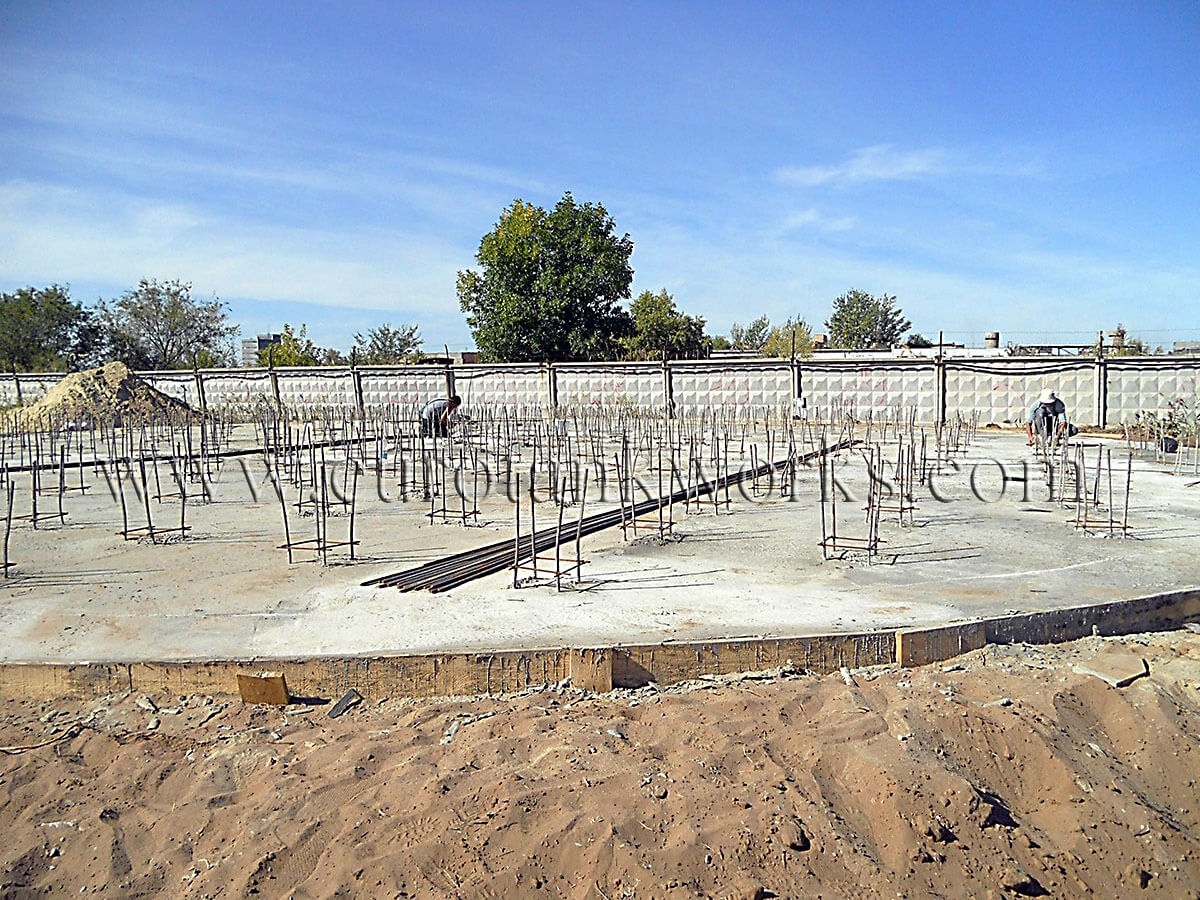
This is supposed to be achieved by the use of prismatic driven piles of various length and cross-section in combination with grillage and slabs. The piles are, as a rule, installed under the whole bottom in the form of the complete pile field, each pile is at distance of 1 m from the other.

Foundations with piles under the whole bottom and with intermediate beddingare also used. Here a layer of crushed stone or granular material is put over the piles and serves instead of the iron-concrete coat.

3.2.3 Ring piled foundation

It is an effective solution for sites with soft soil.

The ring monolithic iron-concrete foundation takes the load of the tank wall and transfers it to the dense soil of low compressibility through either of the following schemes:

  • Crushed stone cushion,
  • Concrete foundation mattress
  • Monolithic iron-concrete grillage,
  • Two rows of tightly fixed piles.

This structure enables to reduce the unevenness of the basement subsidence under the tank wall.

3.2.4. Ring piled foundation with shifting (displacement):

It is used as an improved version of ring piled foundation.

Displacing of the monolithic iron-concrete ring and the ring piled foundation in relation to the tank wall is considered one of the solutions of tank subsidence problems. The rate of displacing is determined depending on local characteristics of soil basement, construction load and the number of piles’ rows in the grillage.

This can result in sufficient decrease of unevenness of subsidence along the tank perimeter and the whole structure within the operating life period.

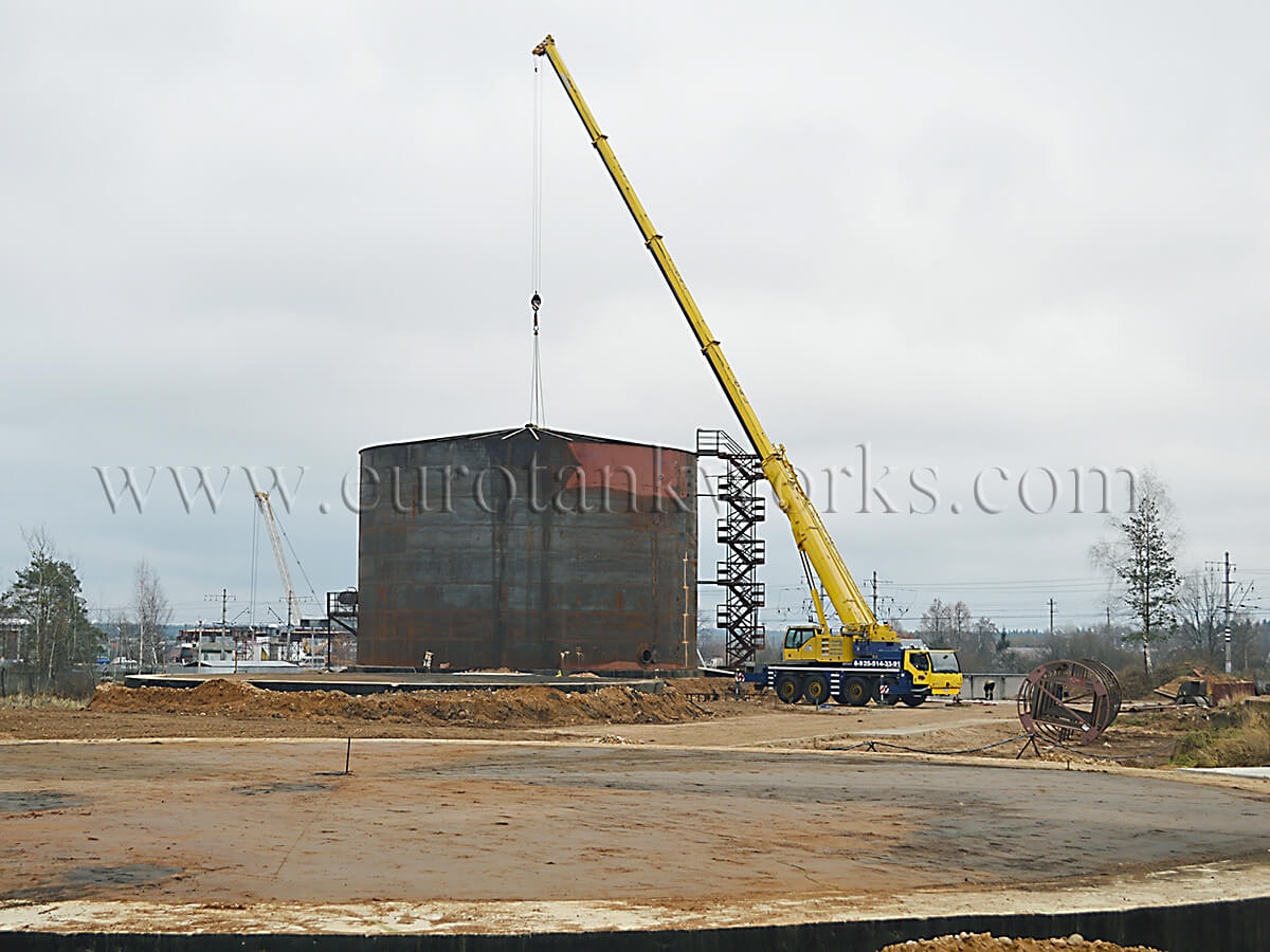
In the course of arranging this type of foundation the soil basement is planned, the piles are installed at the planned point, their location is determined depending on local characteristics of the soil basement, structure load and the number of piles’ rows in the grillage. The monolithic iron-concrete ring grillage is installed on pile-heads, after that the crushed stone bedding is arranged, on which the monolithic iron-concrete ring is put. The sand cushion is planned and arranged under the tank bottom, then the metal frameworks of the tank are assembled.

3.3. OIL STORAGE TANK FOUNDATION DESIGN FOR THE DIFFICULT GEOLOGIC CONDITIONS:

3.3.1. Iron-concrete strip reinforced foundation

It is reasonable to consider the rigidness of the ring foundation in case of thick soft soil in order to ensure avoiding sufficient uneven subsidence of the natural base. In this situation it is possible to use massive strip iron-concrete foundation under the wall of the tank, which gives additional rigidness to the structure along its perimeter.

The height of the foundation is determined based on putting the foundation base lower the level of seasonal freezing of the soil.

It may be reasonable to arrange a crushed stone cushion to reduce the height of the foundation and to transfer the load from the tank to the foundation. As the load in this case is low, the area of the foundation’s cross section may be relatively small. The sides of the foundation are covered with non-frost heaving material.

If sufficient uneven subsidence occurs along the perimeter, such foundation gives opportunity to level the edge of the tank. To achieve this it is possible to arrange a catch pit (dibhole) in the crushed stone cushion, meant for placing the pulling up device (e.g. casing puller or jack), based on the iron concrete foundation. After the edge of the tank is pulled up to the needed level the pulling up device is removed and the catch pit is back filled.

The use of unitized iron-concrete elements enables to reduce the amount of wet processes in the course of performing the work and to increase labor efficiency of the initial construction work (“zero” cycle).

3.3.2. Iron-concrete ring at the external outline of the wall

Reinforcement of the shell-to-bottom junction


When filling the large volume tanks there is a joint moment appearing at the point of junction of the wall to the bottom. This joint moment amounts to sufficient size and influences the strain-distorted condition of the bottom and its basement. To reduce the torsion moment (twisting moment) and to increase rigidness of the “wall-bottom” joint it is suggested to use iron-concrete ring, arranged at the external outline of the tank wall together with metal stiffening rings in the form of angle braces (see pic. 6). Their number is determined by constructing or calculating, which depends on the tank’s loading capacity.


3.4. PILED STORAGE TANK FOUNDATION DESIGN FOR THE SEISMIC AREAS

Piled foundations in seismic areas are applied in the same way as in areas which show no seismic activity. It is necessary to meet the requirements of СП 50-102-3003 «Engineering design and arranging of piled foundations”, in particular – part 12 “Specific features of design planning of piled foundations in seismic areas” and supplement D “Pile calculation for combined impact of vertical and horizontal forces and moment”.

The lower ends of piles should be based on rocky soil, macrofragmental soil, sand soil of high and medium density, hard and stiff soil, low plasticity clay soil. It is not allowed to place the bottom edges of the piles in seismic areas on loose water saturated sand, plastic clay, soil of high plasticity and free-flowing consistency.

Supporting of piles by inclined shelves of hard rock and psephitic rock is allowed only when the soil’s seismic impact stability is provided not by the piled foundation and if there is no chance for the piles’ bottom edges to slip.

It is allowed to put the piles on water saturated sand of high and medium density. Their bearing capacity at the same time should be determined based on results of piles’ field testing for simulated seismic impact. Piles in seismic areas should be sunk in soil for not less than 4 m, excluding the cases when they are supported by hard rock soil.

Cast-in-place piles in seismic areas should be arranged in cohesive soil of low humidity with the piles’ diameter not less than 40 sm. The ration of their length to the diameter should not exceed 25. It is necessary to have strict quality control, arranged for the piles’ production.

It is exceptionally allowed to cut the layers of water saturated soil with removable case pipes (drive pipes) and clay mud. In case of structurally unstable soil cast-in-place piles can be used only with case pipes, left in the soil.Reinforcing of the cast-in-place piles is essential, the rate of reinforcement is accepted not less than 0.05.

Calculation of piled foundation in seismic impact is done at the extreme states of the first group. It usually includes:

  • Determining pile bearing capacity to the vertical load;
  • Testing the piles for metal resistance to the joint action of rated normal force of deflection moment and the shearing force;
  • Checking the piles’ resistance to limitation of pressure, transferred to the soil by the side edges of the piles.

When the stability of soil around the pile is checked, the estimated angle of shearing resistance is taken decreased by the following rates:

  • 2 ° for seismic activity of 7 balls,
  • 4 ° for seismic activity of 8 balls,
  • 7 ° for seismic activity of 9 balls.

For foundations with high pile grillage the calculated rates of seismic forces should be determined like for buildings with flexible bottom part.Dynamic factor should be increased 1.5 times in cases when the period of natural vibrations of the basic tone is equal to 0.4 and more.

Provided that there is acceptable technical-economic reasoning, it is possible to use piled foundations with intermediate cushion of loose materials – crushed stone, gravel, coarse sand. The possibility to transfer the horizontal load from the vibrating construction to the pile is practically eliminated. That is why calculations for horizontal seismic load are not made and the structure of piles is accepted the same as in non-seismic areas.

The foundation block, installed on the intermediate cushion, is planned as grillage of an ordinary piled foundation in accordance with the standards for engineering design of concrete and iron concrete constructions.

Arranging iron-concrete pile-heads may help to increase the area of contact.

Piled foundations with intermediate cushion, applied in seismic areas, should meet the requirements of the deformation evaluations.The thickness of the intermediate cushion above the pile heads depends on the estimated load and amounts to 40-60 sm.

Calculations of piled foundations on subsiding soil should consider the characteristics of wet soil in case there is possibility of ground water level increase.

Storage Tank Foundation Construction
To order