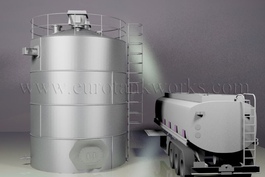
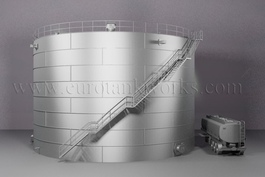
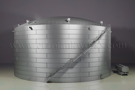
TYPICAL AST TANKS SIZES AND CHARACTERISTICS:
|
Type and loading capacity of the tank,
m³
|
Diameter,
m |
Height,
m |
Shell Net weight, t |
Bottom Net weight, t |
Roof Net weight, t |
Other structures’ Net weight, t |
Frame and packing Net weight, t |
Total Tank Net weight, t |
| Vertical steel tank 100 m3 |
4,73 |
6,0 |
3,60 |
0,76 |
0,87 |
2,14 |
2,10 |
9,47 |
| Vertical steel tank 200 m3 |
6,63 |
6,0 |
50,3 |
1,47 |
1,69 |
2,47 |
2,10 |
12,77 |
| Vertical steel tank 300 m3 |
7,58 |
7,5 |
7,18 |
1,95 |
2,34 |
2,84 |
2,30 |
16,61 |
| Vertical steel tank 400 m3 |
8,53 |
7,5 |
8,04 |
2,40 |
2,66 |
3,60 |
2,30 |
19,01 |
| Vertical steel tank 500 m3 |
8,45 |
9,3 |
11,75 |
3,48 |
5,05 |
3,76 |
2,30 |
26,34 |
| Vertical steel tank 700 m3 |
10,43 |
9,0 |
11,75 |
3,58 |
5,08 |
5,55 |
3,20 |
29,16 |
| Vertical steel tank 1000 m3 |
10,43 |
12,0 |
16,51 |
3,47 |
5,01 |
5,86 |
3,80 |
34,67 |
| Vertical steel tank 2000 m3 |
15,18 |
12,0 |
25,08 |
8,46 |
13,84 |
6,16 |
5,20 |
58,74 |
| Vertical steel tank 3000 m3 |
18,98 |
12,0 |
38,60 |
13,43 |
22,80 |
7,38 |
5,70 |
87,91 |
| Vertical steel tank 5000 m3 |
20,92 |
15,0 |
64,42 |
17,73 |
26,20 |
8,42 |
10,80 |
127,57 |
| |
22,8 |
12,0 |
54,10 |
18,98 |
33,95 |
8,61 |
7,80 |
23,43 |
| Vertical steel tank 10000 m3 |
28,5 |
17,9 |
86,72 |
42,15 |
78,61 |
12,82 |
14,00 |
234,30 |
| |
34,2 |
12,0 |
120,92 |
30,90 |
54,65 |
12,28 |
21,48 |
240,23 |
| Vertical steel tank 20000 m3 |
39,9 |
17,9 |
225,14 |
57,41 |
106,05 |
16,78 |
27,37 |
432,74 |
| Vertical steel tank 30000 m3 |
45,6 |
18,0 |
284,25 |
91,42 |
145,47 |
30,16 |
44,10 |
595,40 |
| Vertical steel tank 50000 m3 |
60,7 |
18,0 |
431,91 |
154,23 |
325,05 |
16,09 |
67,00 |
994,29 |
TYPES OF VERTICAL ABOVE-GROUND STORAGE TANKS:
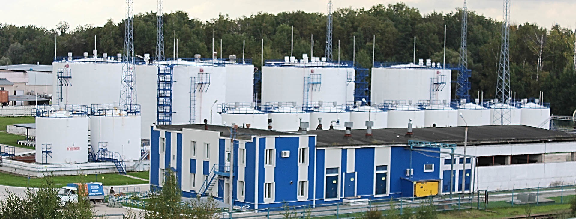
The choice of the AST storage tank type depends on the stored product, specific features of the technological cycle of the enterprise and the characteristics of the installation site.
There are 4 basic types of vertical steel tanks:
- Vertical steel fixed roof tanks without a pontoon;
- Vertical steel fixed roof tank with a pontoon;
- Vertical oil tank with floating roof;
- Tanks with protective wall.
Vertical AST storage tank with fixed roof without pontoon.
These tanks are meant for storing products with relatively low volatility (saturated vapour pressure not more than 26.6 kPa), and the burning point exceeding 61°С. Such tanks are often used for storing fuel oil, diesel fuel, kerosene oil of utility type, bitumen, flux, oils (including food oils) and water (firefighting tank and water stock tanks). Vertical steel tanks with fixed roof without pontoon may be applied in storing more volatile and inflammable products (saturated vapour pressure up to 93,3 kPa). In these cases the tanks are equipped with gas piping and the light end recovery apparatus.
Vertical site built storage tanks with fixed roof and pontoon.
These large storage tanks are meant for storing products with saturated vapour pressure kept in the limits between 26.6 and 93.3 kPa. Such tanks are most often used for storing oil, petrol, kerosene oils, jet fuel. A pontoon is a rigid gas proof floating disc-shaped cover, inserted in the tank body on the product surface in such a way as to cover not less than 90 % of the surface. The annular clearance between the pontoon and the tank wall is sealed off with special rim seal. The Pontoon is supposed to lower the saturation rate of the steam-and-gas zone with the stored product’s fumes. Pontoon is also known as Internal floating roof.
Vertical floating roof storage tanks.
This version of tank implies the use of roof that floats on the stored product’s surface in full contact. The floatability of the roof is achieved by applying leak-proof frame bays or buckets. In an empty tank the roof is placed on special supporting structures, installed at the bottom. Rotation is avoided, because the guide columns are used. The disadvantage of the floating roof is to be seen in the possibility of the stored product’s contamination of precipitate. There are certain cases, when the rim seal of the roof may also freeze to the tank wall. Advantages of this construction scheme are mainly in the reduction of the product loss because of vaporization.
Site built storage tanks with protective wall.
These tanks are used at production sites where bunds of a tank farm are impossible to install. Such tanks are also located near water basins and in urban areas for environment and people’s protection purposes. The protective wall is installed for the sake of avoiding the product’s outpour and the tank unsealing.
Vertical SITE BUILT STORAGE tanks fabrication methods:
There are two basic methods of manufacturing vertical steel tanks:
1. Coiling method:
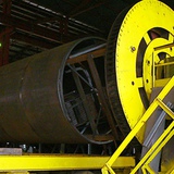
This method implies that tank wall, bottom and roof are brought to the construction site in the form of coiled strip panels, meant for welding. The advantages of this method are to be seen in:
- making the tank installation period 3-4 times shorter as a result of cutting down the volume of welding procedures at the construction site by about 80 % at the average;
- providing high quality of welding joints due to the use of two-side automatic welding at the workshop.
Strip panels are produced from steel sheets of modular size 1500×6000 mm. Panels are automatically welded on a special coiling machine.
2. Plate-by-plate method:
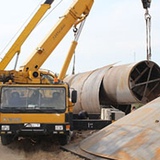
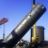
This method implies that the wall sheets of maximum size 2500×10000 mm and the bottom plates are prepared at the workshop, they are rolled to the radius, stipulated by the design project. Then the plate elements are packed in a special way to be prepared for transportation. Wall and bottom assembly (welding) is carried out on the construction site.
Vertical steel storage tanks can be fabricated of mild steel, low-alloyed or stainless steel.
Construction elements of a large storage tank
Tank bottom
Vertical above-ground storage tank bottoms are made of steel with 4 mm thickness at the minimum. In low loading capacity tanks (up to 1000 m³ included) bottoms are usually flat-shaped. For tanks of loading capacity exceeding 1000 m³ the bottom is made with an inclination from or to the center at the rate of 1:100. A ring-shaped edge is installed on the bottom of vertical steel tanks with loading capacity exceeding 1000 m³. The edge steel thickness is from 6 mm and more, which depends on the thickness of the lower ring. The dependency connection is shown in the table below:
| The lower ring thickness |
Minimum thickness of the annular edge |
| till 7 mm (up to inclusive) |
6 mm |
| 8 mm — 11 mm (up to inclusive) |
7 mm |
| 12 mm – 16 mm (up to inclusive) |
9 mm |
| 17 mm – 20 mm (up to inclusive) |
12 mm |
| 20 mm – 26 mm (up to inclusive) |
14 mm |
| 26 mm and more |
16 mm |
The vertical oil tank bottom is often equipped with stripping sink holes (sump). They are installed in a special catch pit and are meant for bottom water, inclusions and different sedimentations drainage. If the inclination of the bottom is made to the center, the stripping sink hole is located at the center; if the inclination is from the center (as well as in case of flat bottom) the sump is located next to the wall at 600 mm distance and more. There are basically two types of sink holes: round-shaped and tray-type.
Vertical steel storage tank shell
The tank shell is a steel strip panel, welded from the sheet metal in several rings. The coiling method implies that the shell is manufactured at the workshop in the shape of a rectangular strip-panel, welded from the metal plates 1.5×6 m. Vertical sheet joints have a stagger, while the longitudinal seams are prepared for saw-tooth joint. The strip panel has a certain bulk (excess metal) up to 300 mm, from which the toothed assembly joint is cut. The plate-by-plate method fabrication applies metal plates with the width between 1.8 and 3 m and up to 12 m long. Sheet edges processing is carried out by mechanical method (milling) or plasma cutting on the program control equipment. The sheets’ rolling is done on 3- or 4-rolls’ sheet bending machines.
Shell thicknesses
Thickness of the rings is determined at the planning stages to ensure durability of the whole installation. Estimated thickness of the rings may include corrosion allowance.
| Diameter of tank |
Thickness |
| 16 m (up to inclusive) |
5 mm |
| 16 m – 25 m (up to inclusive) |
6 mm |
| 25 m - 40 m (up to inclusive) |
8 mm |
| 40 m – 65 m (up to inclusive) |
10 mm |
| 65 m and more |
12 mm |
Installation of manway plates and pup joints in the tank shell
For the purpose of installation of manway plates and pup joints in the shell of the tank special holes are provided, which are enforced by a cover plate round the installed unit (in case of installation of the units with the pipe size more than 70 mm). An access manway plate is provided in the first wall ring in all vertical tanks. Tanks with floating roof and tanks with pontoon are equipped with additional manway plate to give access to the pontoon and the roof.
Anchor clamping of the shell
Anchor clamping of the shell is located in full circle around the wall at 3 m distance from each other. They are added to the construction scheme in cases, when the impact of estimated seismic or wind stress exceeds the stabilizing moment.
Vertical oil tank roof
As regards the type and size of the AST storage tank and other specific features the roofs are divided into fixed-site type and floating type. Fixed-site roofs can be represented either by frameless (self-supporting) or framed roofs in conical or spherical shape. The roof is based on the tank wall with a ring-shaped stiffening plate. The thickness of roof decking and cross-section of the frame elements are designed from 5 mm.
Cone covering (conical frameless roof)
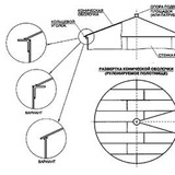
It is applied for on-site fuel tanks of low loading capacity (100 m³ — 1000 m³). This is a fixed roof of conical shape. The conical angle (15° — 30°) provides the supporting capacity of the roof which is increased by adding structural rings on the outside. The roof decking is fabricated at the workshop by either coiling or per-sheet method. The first demands metal plates up to 7 mm in thickness, the second method implies the use of metal plates up to 10 mm. As a rule, conical frameless roofs are brought to the construction site as a round plate with sector porthole. This porthole provides the conical shape when the edges are attached to each other in the course of installation.
Spherical covering (frameless spherical roof)
It is applied for site built storage tanks of medium loading capacity (1000 m³ — 5000 m³). This is a fixed-site roof of spherical shape, which provides its supporting capacity. There are no supporting elements of the frame. The sphere radius is planned within the limits of 0.8-1.2 of the tank diameter. The spherical covering decking is fabricated at the workshop in the form of rolled elements of double curvature (in East-West and circular direction) from metal plates up to 10 mm thick. The rolled elements are welded to each other with two-side joints at the construction site.
Framed cone roof
It is applied in vertical steel tanks of medium loading capacity (1000 m³ — 5000 m³). This is a fixed-site roof of conical shape. The inclination angle is equal to 4.76º — 9.46º. These roofs consist of: (1) central panel; (2) sector frame; (3) ring-shaped frame elements; (4) decking strip panels.
All above mentioned elements are produced at the factory. The decking strip panels may be manufactured by coiling method. In this case they are unfolded on the ground near the bottom and then attached to the joint frames. The decking strip panels may also be produced by per-sheet method. It is also a usual practice to manufacture the roof panels, consisting of frame and decking elements, attached to each other. In this case the roof panels are brought to the construction site specially packed.
Conical framed roof may be constructed in explosion-preventive version (easy-to-remove roof).The roof decking is not welded to the frame in this case, but remains attached only to the upper ring element of the wall. This enables the decking to be torn off the wall in case of emergency pressure increase inside the body of the tank. The tank itself is not destroyed and the joint of the wall to the bottom remains safe.
Spherical framed roof (domed roof)
It is applied in large storage tanks of high loading capacity (from 5000 m³, but not more than 50 m in diameter). This is a fixed spherical roof with radial-circular type of frame system. The sphere radius is planned within the limits of 0.8-1.5 of the tank diameter. The spherical framed roof consists of: (1) central panel; (2) rolled radial bars; (3) ring-shaped frame elements; (4) stiffening rings along the wall perimeter; (5) decking sheets.
All above mentioned elements are fabricated at the workshop. They are brought to the construction site in the form of finished panels and separate frame and decking elements. The decking is represented by prepared metal sheets for per-sheet assembly, or large-size charts prepared at the factory.
Spherical roofs may also be constructed in explosion-preventive version. The roof decking is attached only to the rim element around the roof. This enables the decking to be torn off the wall in case of emergency pressure increase inside the body of the tank. The tank itself is not destroyed and the joint of the wall to the bottom remains safe.
Floating roofs of storage tanks
They are applied in on-site fuel tanks without fixed roofs. This roof type is to be used in areas with the standard snow load not more than 1.5 kPa.
There are two basic types of floating roofs in the tank production industry: (1) single-deck floating roof (2) double-deck floating roof.
Single-deck floating roofs are meant for middle-sized tanks (up to 50 m in diameter), installed at the production sites with the standard wind speed within the limits of 100 km/h.
Single-deck floating roofs are produced at the factory and consist of:
- Sheet diaphragm, produced by either coiling of per-sheet method;
- Ring buckets, located along the perimeter.
Double-deck floating roofs are designed for tanks of a bigger diameter (more than 50 m) and for the areas with higher wind stress. Its construction scheme enables to reduce the dynamic load of the diaphragm. There are two variants of producing a floating roof of this type: (1) the roof is provided with radial and circular frame bays of the central part, that are made in the course of installation; (2) radial buckets are fabricated at the workshop as a means of reducing the scope of assembly procedures.
While installing the floating roof the inclination of the diaphragm to the center is provided by tightening weight. This enables to drain the runoff waters from the roof surface. A flexible or swinging water outlet is installed in the center, with an intake and a backpressure valve. This construction scheme makes it possible to drain water and to avoid emergence of the stored product to the roof surface.
The air gaps between the edge of the floating roof and the tank wall, between the pup joints and guide frames are made leak-proof with the help of rim seals. Material for their production is to be chosen as regards the chemical composition and the temperature of the stored product, operating life requirements, gas mass density and other specific factors
Staircases, platforms and passages for site built storage tanks
Staircases
Either of three types of staircases can be used in an on-site fuel tank: stepladders for low loading capacity tanks (up to 500 m³), shaft staircases and circular-type staircases.
Shaft staircases are installed on a separate base plate. For tanks produced by coiling method this staircase serves as a technological frame (coil) on which the welded wall strip panels, bottom and roof decking are rolled. This helps to cut down the cost of the unit because there is no need to produce technological frame, which is an expendable packing.
Circular-type staircase is fixed only to the tank wall, its lower flight starts at 250 mm higher the ground level. This construction scheme is considered to be more convenient for tank equipment service.
Vertical tanks staircases’ minimum width is 700 mm. The inclination to the horizontal surface is not more than 50° and they have to be installed in a way as to stand the single point load of 4,5 kN. If the height of the staircase exceeds 9 m, its design project includes midpoint plates at the distance not more than 6 m from each other.
The steps are made of punched, grid or riffled metal minimum 200 wide, not more than 250 mm high and with the inclination rate from 2° to 5° to the back edge. The railings are made in a way to stand the horizontal load of 0.9 kN at the top point and are 1 m higher the steps.
Platforms, passages and fencing
Fencing is installed on vertical tanks with a fixed roof around its perimeter. They are located on the outside of the service decks on the tank roof. Fencing is designed to stand a load of 0.9 kN in any direction at any point.
On-site fuel tanks also have passages and service platforms. They are supported by railings at 1.25 m height. Platforms and passages stand the single point load of 4.5 kN (for platform dimensions 100 mm x 100 mm).
You may also be interested:
>>> Hot Water Storage Tanks (Buffer Tanks)
>>> Grain Silos
>>> Cement Silos
